
23 Module 22 Sweeping
Öğrenme Sonuçları
Bu modülün tamamını gerçekleştirebileceksiniz:
- Kapalı bir profil bir yol boyunca süpürerek katı modeller oluşturmak için SWEEP alanını açıklayın ve modüle edin.
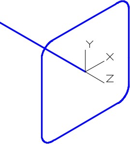
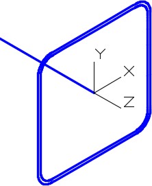
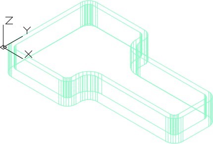
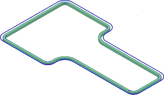
Süpürmeler
Süpürmeler , oluşumu bir yol boyunca bir veya daha fazla profil süpürerek (hareket ettirerek) oluşur. Şekil 22-1 ve 22-2’ye bakın. Yol, açık veya kapalı bir çizim nesnesi olabilir ancak tek bir nesne olmalıdır. Profil kapalı bir nesneyse, süpürme bir katı oluşturacaktır. Profil açık bir nesneyse, süpürme bir yüzey oluşturacaktır.
Süpürmeler, boru, küvet, drenaj borusu, contaları ve dişler gibi modeller oluşturmak için kullanılır.
Bir Tarama Profili ve Yolu
Yol için nesnelerin nesneleri 2B ve 3B eğriler, 2B ve 3B poli çizgiler, katılar, yüzeyler ve ağ kenarı alt nesneler, sarmallar, yaylar, daireler, elipsler, eliptik yaylar ve çizgilerdir.
Profil için ekonomik nesneler 2B ve 3B eğriler, 2B poli çizgiler, 2B katılar, 3B katı yüz alt nesneler, yaylar, daireler, elipsler, eliptik yaylar, çizgiler, bölgesel, katılar, yüzey örgü kenarı alt görünümler ve izlerdir.
DELOBJ sistem değişkeni, SWEEP komutunda kullanılan orijinal profil ve yol geometrisini otomatik olarak silmek veya tutmak için kullanılabilir.
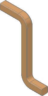
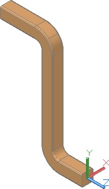
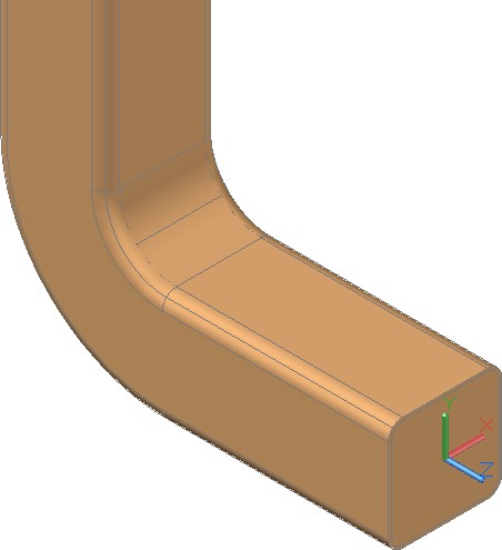
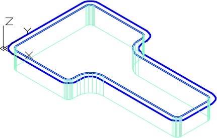
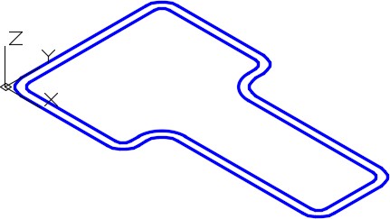
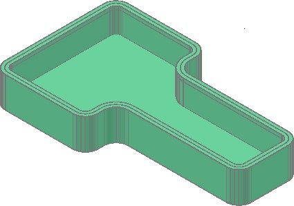
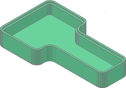
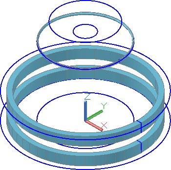
Süpürme Uygulandıktan Sonra Tamamlanmış Katı Model
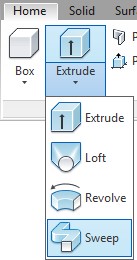
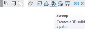
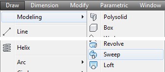
AutoCAD Komutu: SÜPÜRME
SWEEP tuşu, bir profil boyunca bir yol süpürerek 3 boyutlu katı veya yüzey modeli oluşturmak için kullanılır.
Kısayol: özellikleri
WORK ALONG: SWEEP Komutunu Kullanma – Bölüm 1
Adım 1
YENİ oranını kullanarak, 3D Düzen Türkçe şablonunu kullanarak yeni bir çizime başlayın.
Adım 2
Çizimi kaydetme ve adlandırmanın: AutoCAD 3D Workalong 22-1 . (Şekil Adım 2A, 2B ve 2C)
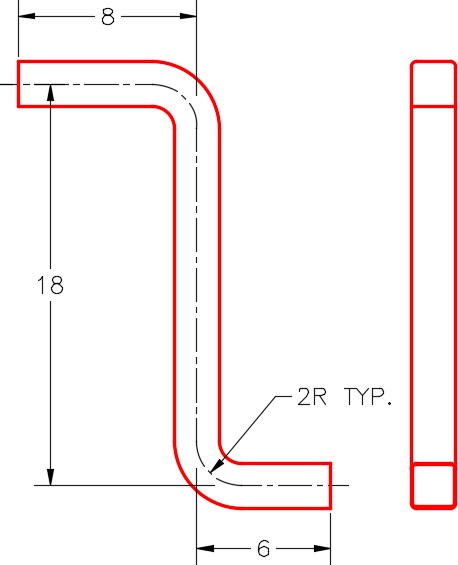
Boyutlandırılmış Çoklu Görünüm Çizimi

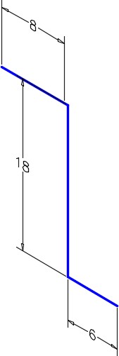
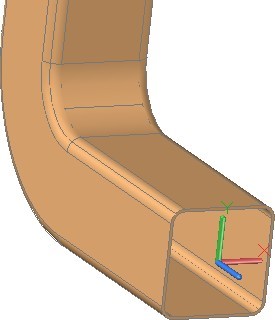
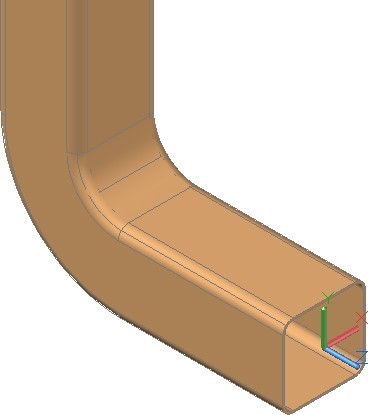
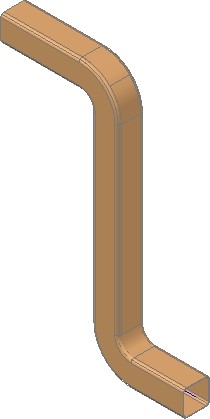
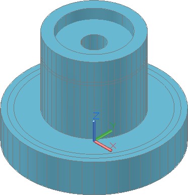
Tamamlanmış 3D Katı
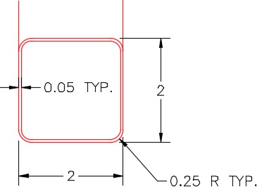
Açıklığın Boyutlandırılmış Detayı
Adım 3
DELOBJ sistem değişkeninin 0 olarak ayarlandığından emin olun.
Adım 4
Görsel stilini 3D Wireframe olarak ayarlandı.
Adım 5
Katmanı düzenlenir: Yolu geçerli katman, güncel görünümü SE İzometrik ve geçerli UCS’yi Ön olarak ayarlanır.
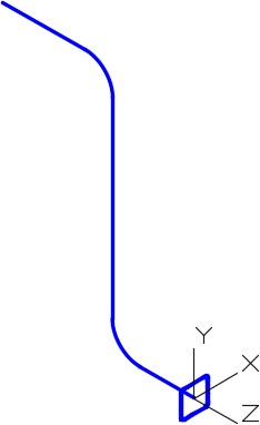
Adım 6
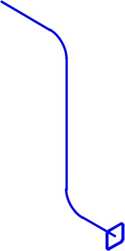
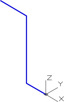
Şekil Adım 2A’yı referans olarak kullanarak, Orto modunu etkinleştirin, ön UCS’de bir pline çizmek için aşağıda gösterildiği gibi PLINE özelliğine girin. Pline’ı 0,0,0’dan başlatın. (Şekil Adım 6A ve 6B)
Komut: PLINE
Başlangıç noktasını gösteriyor: 0,0,0
Mevcut satır genişliği 0,0000’dır
Sonraki noktayı veya [Yay/Yarım Genişlik/Uzunluk/Geri Al/Genişlik] yayınlandı: <Orto açık> 6
Sonraki noktayı açıkladı veya [Yay/Kapat/Yarım Genişlik/Uzunluk/Geri Al/Genişlik]: 18
Sonraki noktayı belirtin veya [Yay/Kapat/Yarım Genişlik/Uzunluk/Geri Al/Genişlik]: 8
Sonraki noktayı veya [Yay/Kapat/Yarım Genişlik/Uzunluk/Geri Al/Genişlik] öğesini belirtin:
Emretmek:
Adım 7
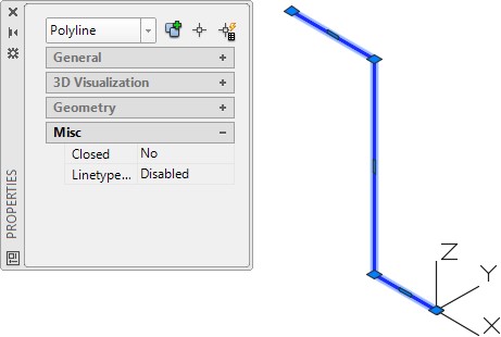
Özellikler pencerelerini kullanarak nesnenin tek bir poli çizgi olduğundan emin olun. (Şekil Adım 7)
Step 8
Using the FILLET command and the Polyline option, as shown below, fillet the corners with a radius of 2. (Figure Step 8)
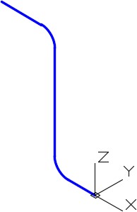
Command: FILLET
Current settings: Mode = TRIM, Radius = 0.0000
Select first object or [Undo/Polyline/Radius/Trim/Multiple]: R
Specify fillet radius <0.0000>: 2
Select first object or [Undo/Polyline/Radius/Trim/Multiple]: P
Select 2D polyline:
(Select the polyline.)
2 lines were filleted
Command:
Step 9
Set layer: Profile as the current layer and the current UCS to Right.
Step 10
Using the Figure Step 2C as a reference, draw a closed pline with its centre at the end of the path. The pline is 2 inches square. (Figure Step 10)
Step 11
Using what you learned earlier in the workalong, fillet the four corners of the pline with a radius of 0.25. (Figure Step 11)
Step 12
Using what you learned earlier, use the Properties windows and insure that object is a closed polyline.
Step 13
Offset the pline, towards the inside, at a distance of 0.05 inches. (Figure Step 13A and 13B)
Step 14
Set layer: Solid 4 as the current layer and the current visual style to Realistic.
Step 15
Use the SWEEP command, as shown below, to sweep both profiles along the path in one command. (Figure Step 15A and 15B)
Command: SWEEP
Current wire frame density: ISOLINES=4, Closed profiles creation mode = Solid
Select objects to sweep or [MOde]: 1 found
(Select one profile.)
Select objects to sweep or [MOde]: 1 found, 2 total
(Select the other profile.)
Select objects to sweep or [Mode]:
(Press Enter)
Select sweep path or [Alignment/Base point/Scale/Twist]:
(Select the path.)
Command:
Step 16
Turn layers: Path and Profile off.
Step 17
Using what you learned earlier in the book, use the SUBTRACT command to subtract the inner solid from the outer solid. (Figure Step 17A, 17B, and 17C)
Step 18
Save and close the drawing.
WORK ALONG: Using the SWEEP Command – Part 2
Step 1
Using the NEW command, start a new drawing using template: 3D Layout Metric.
Step 2
Save and name the drawing: AutoCAD 3D Workalong 22-2. (Figure Step 2)
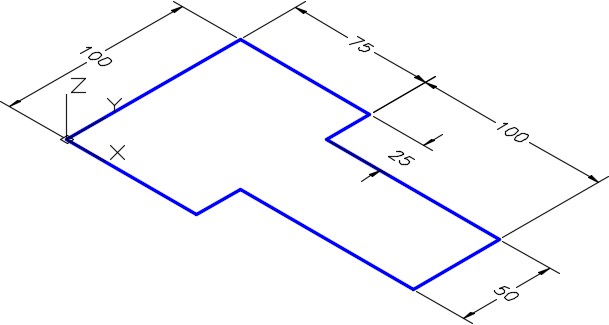
Dimensioned Drawing
Step 3
Set the current view to SE Isometric, the current UCS to World.
Step 4
Path as the current layer, and the current visual style to 2D Wireframe.
Step 5
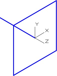
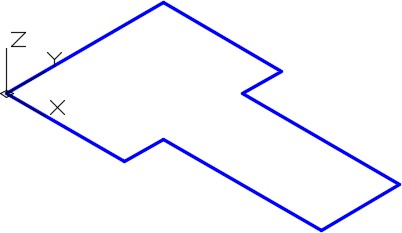
Using Figure Step 2 as a reference, draw a closed pline as shown in the figure. (Figure Step 5)
Step 6
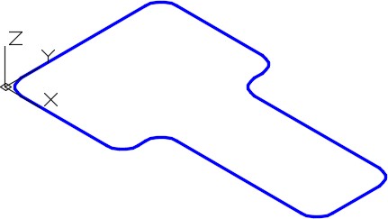
Using what you learned in the first workalong, fillet all of the corners, in one step, with a radius of 10. (Figure Step 6)
Step 7
Offset the closed pline 5 mm towards the inside. (Figure Step 7)

Step 8
Set the system variable ISOLINES to 24.
Step 9
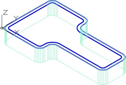
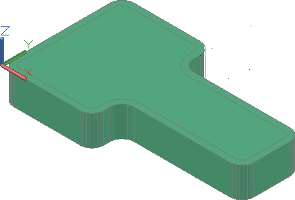
Set layer: Solid 1 as the current layer. Extrude the outer pline 25 mm in the negative Z. (Figure Step 9)
Step 10
Freeze layer: Solid Off. Change the layer of the extruded outer solid that you created in Step 9 to layer: Solid Off.
Step 11
Extrude the inner pline 20 mm in the negative Z. (Figure Step 11)
Step 12
Change the layer of the first solid from layer: Solid Off to layer: Solid 1. Turn layer: Path off. Your drawing should match the figure. (Figure Step 12)
Step 13
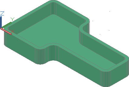
Change the visual style to Realistic. (Figure Step 13)
Step 14
Using the SUBTRACT command, subtract the inner solid from the outer solid. (Figure Step 14)
Step 15
Change the layer of the solid on layer: Solid 1 to layer: Solid Off. Turn layer: Path on and set layer: Profile as the current layer. Set the visual style to 2D wireframe. (Figure Step 15)
Step 16
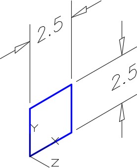
Change the current UCS to Right.
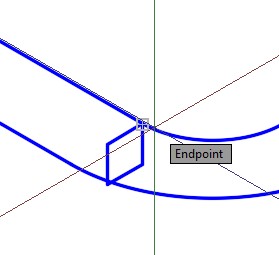
Step 17
Draw a closed pline 2.5 x 2.5 inches. Start it by snapping to endpoint of the inner pline. (Figure Step 17A, 17B, and 17C)
Step 18
Set layer: Solid 1 as the current layer.
Step 19
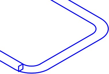
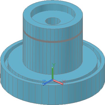
Using the SWEEP command, sweep the 2.5 inch closed pline using the inner pline as the path. (Figure Step 19)
Step 20
Change the layer of the solid on layer: Solid Off to layer: Solid 1. Turn layers: Path and Profile off and change the visual style to Realistic. (Figure Step 20)
Step 21
Using the SUBTRACT command, subtract the solid that was created using the SWEEP command from the original solid. (Figure Step 21)
Step 22
Save and close the drawing.
Key Principles
Key Principles in Module 22
- Sweeps are created by sweeping (moving) one or more profiles along a selected path. The path can be an open or closed object but must be one object. If the profile is a closed object, the sweep will create a solid. If the profile is an open object, the sweep will create a surface.
Lab Exercise 22-1
Time allowed: 60 minutes.
| Drawing Name | Template | Units |
|---|---|---|
| AutoCAD 3D Lab 22-1 | 3D Layout English | Inches |
Step 1
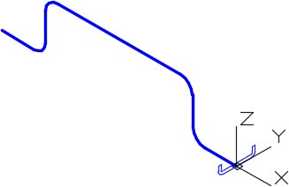
On layer: Profile, draw the profile as a closed pline and on layer: Path, draw the path as a single pline. (Figure Step 1A and 1B)
Step 2
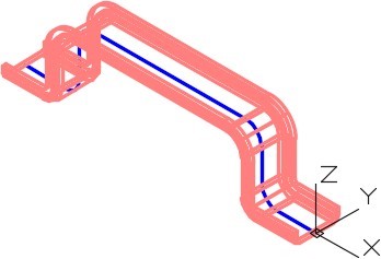
On layer: Solid 6, create the solid using the SWEEP command.
Step 3
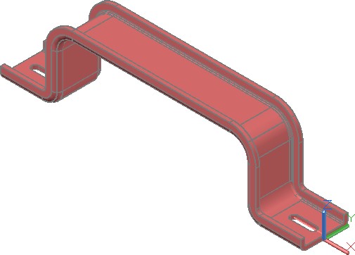
Create the slots by first creating one and mirror it to create the opposite slot. Subtract them to complete the object.
Step 4
Save and close the drawing.
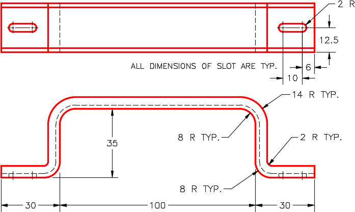
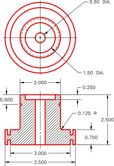
Dimensioned Multiview Drawing
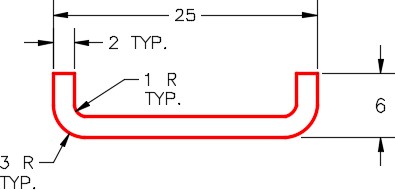
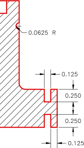
Detail of Right Side View

Lab Exercise 22-2
Time allowed: 60 minutes.
| Drawing Name | Template | Units |
|---|---|---|
| AutoCAD 3D Lab 22-2 | 3D Layout English | Inches |
Step 1
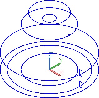
On layer: Path, draw the paths as a circles, and on layer: Profile, draw the closed plines. (Figure Step 1A and 1B)
Step 2
On layer: Solid 3, create the original solid.
Step 3
On layer: Solid 3, create the solids that are to be subtracted using the SWEEP command.
Step 4
Subtract the sweep solids from the original solid.
Boyutlandırılmış Çoklu Görünüm Çizimi
Boyutlandırılmış Detay
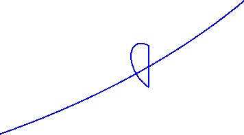
Yay profili bir yay ve çizgi ile oluşturulmalı ve daha sonra kapalı bir pline’a dönüştürülmelidir
Adım 5
Çizimi kaydedin.
