
Module 41: Print Drawings
Output a drawing layout to the printer, plotter or to a file. Save and restore the printer settings for each layout.
In the beginning, people printed texts from printers and drew drawings from plotters. Now, you can do both. Therefore, in this manual we will use the terms print and draw interchangeably, as everyone does.
AutoCAD Command: PLOT
The PLOT command is used to output a drawing.
Shortcut: PRINT

Click the More Options button to control whether all options in the Drawing dialogue box are hidden or displayed.
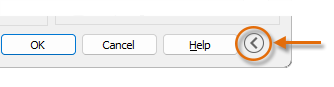
When all options are displayed, there are many settings and options available to you.

You can create your own print templates. You can save these templates with the names you want, create collections and restore these templates. These are called page settings. With page settings you can store the settings you need for different printers, print in greyscale, create a PDF file from your drawing, etc.
Create Page Layout
AutoCAD Command: PAGESETUP
Use the PAGESETUP command to open the Page Setup Manager dialogue box.
Shortcut: none
NOTE: Before selecting Page Setup Manager, make the tab where you want to define the page layout valid.
Each layout tab in your drawing can have an associated page setting. This is useful when you use multiple output devices or formats, or when you have several layouts with different page sizes in the same drawing.
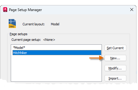
To create a new page setup, click New, enter the name of the new page setup, and click OK. The Page Setup dialogue box that appears next is similar to the Plot dialogue box. Select any options and settings you want to save.
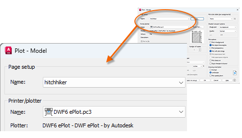
When you are ready to plot, simply specify the name of the page setup in the Plot dialogue box, and all your plot settings are restored. In the following illustration, the Plot dialogue box is set to use the Hitchhiker page setup, which will output a DWF (Design Web Format) file instead of printing to a plotter.
USER TIP: You can save page layouts in your drawing template files or import them from other drawing files.
Output to PDF File
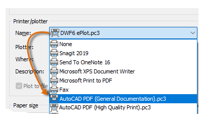
The following example shows how to create a page layout for creating PDF files.
Select AutoCAD PDF (General Documentation).pc3 from the Printer/plotter drop-down list :
Then select the size and scale options you want to use:
- Paper size: Orientation (portrait or landscape) is built into the options in the drop-down list.
- Drawing area: With these options you can crop the area to be drawn, but usually you draw everything.
- Graphics Offset: This setting depends on your printer, plotter, or other output. Try centring the graph or adjusting the origin, but remember that printers and plotters have a built-in margin around the edges.
- Plot Scale: Select your plot scale from the drop-down list. 1/4″ = 1′-0″ A scale, such as a scale, is for printing to scale from the Model tab. On the Layout tab, you normally print at a scale of 1:1.
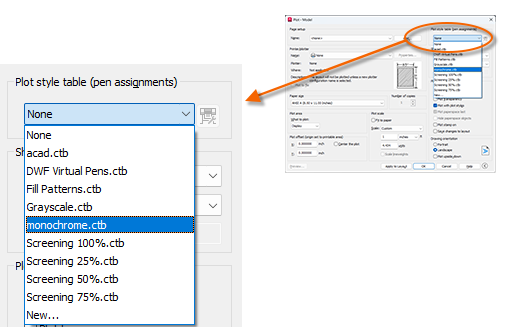
The Artwork style table provides information about colour rendering. Colours that look good on your monitor may not be suitable for a PDF file or for printing. For example, you may want to create a coloured artwork and output it in monochrome. You can specify monochrome output as follows:
USER TIP: Always double-check your settings with Preview.
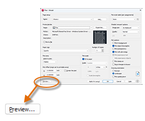
The resulting Preview window contains a toolbar with various controls, including Plot and Close Preview Window.

Once you are satisfied with your drawing settings, save them to a page layout with a descriptive name such as “PDF-monochrome”. Then, when you want to output to a PDF file, simply click Print, select the PDF-monochrome page setup and click OK.
Key Principles
Key Principles in Module 41
- Consistency and Efficiency: Create and save templates for different output devices or formats using page settings (PAGESETUP) to ensure consistency in your drawings and speed up your output process.
- Preview and Control: Always check your drawing settings with the Preview option and make sure your drawing looks the way you want it to before you print.
- PDF Output and Colour Management: Use the drawing style tables (CTB) when creating a PDF file to control how colours appear in the output, and output coloured drawings in black and white or greyscale when needed.
- Page Layout Manager: The PAGESETUP command opens the Page Setup Manager dialogue box, where page settings can be made.
- PLOT Command: A drawing can be output using the PLOT command. In the Plot dialogue box, print and plot settings can be specified and these settings can be saved and used later.
